The summer of second year at UBC's Engineering Physics program is fondly called robot summer, as every student must compete in an intense, robot competition.
This year the competition was based on the game overcooked. The task was to design and build two robots that would work together to assemble fake dishes in a timed setting, similar to the game overcooked.
Mechanical Skills: : CAD (Onsahpe), DFM, laser cutting, and 3D printing
Software Skills: C++, HTTPS communication, Tkinter GUIs, and state machines.
Electrical Skills: System Design, H-Bridges, debouncing (schmitt triggers), and power distribution (buck converters vs LDOs).
Team Members: Ella Yan, Brianna Gopaul, Tristan Brown, Nathan Tourveille
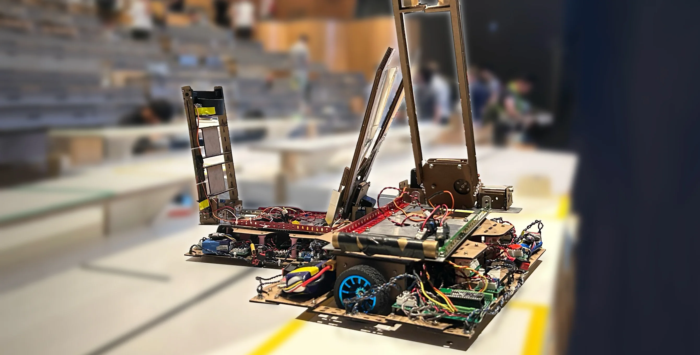
We placed 4th overall which we were somewhat satisfied with. Check out our robot in action below!
Burger Assembly From Start to Finish
First Team to Make a Burger :D
This year's competition was based on the game Overcooked, a game in which, multiple players have to work together to prepare and serve dishes in a timely manner.
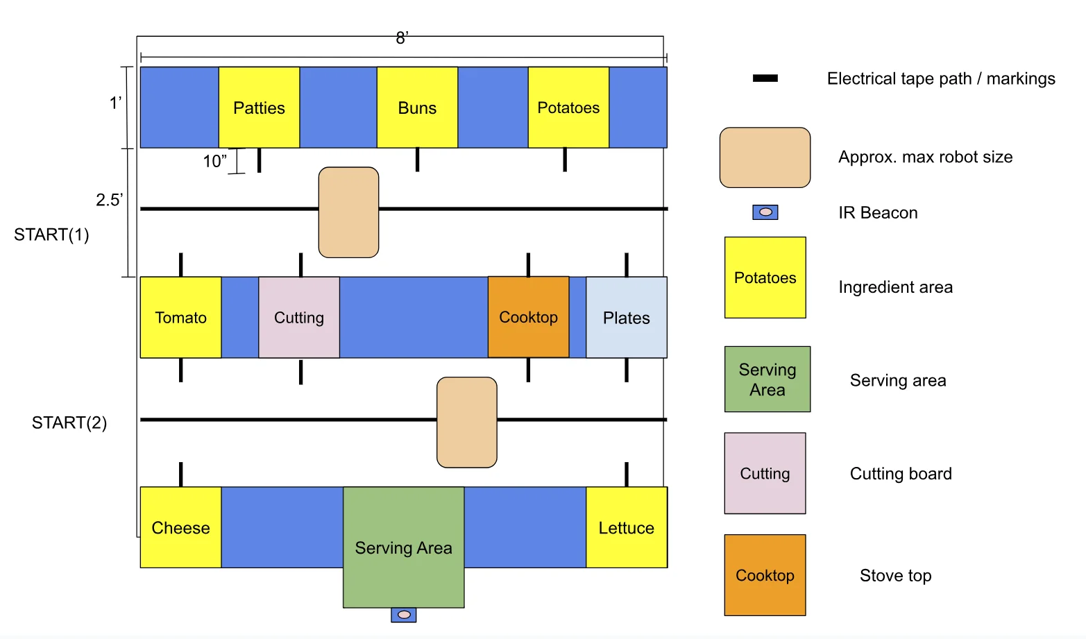
Competition Surface Diagram
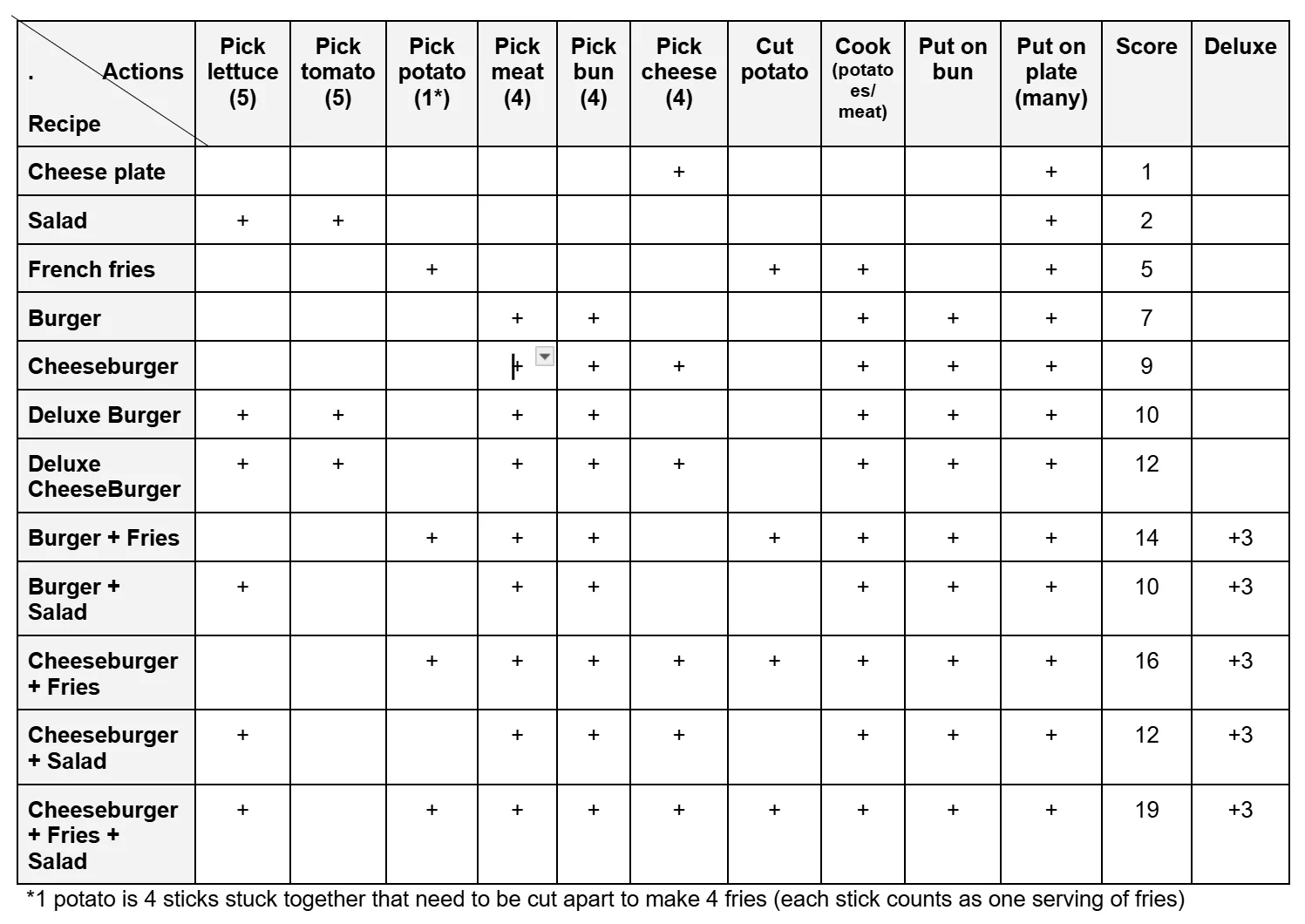
List of Recipes (Deluxe Includes Tomato and Lettuce)
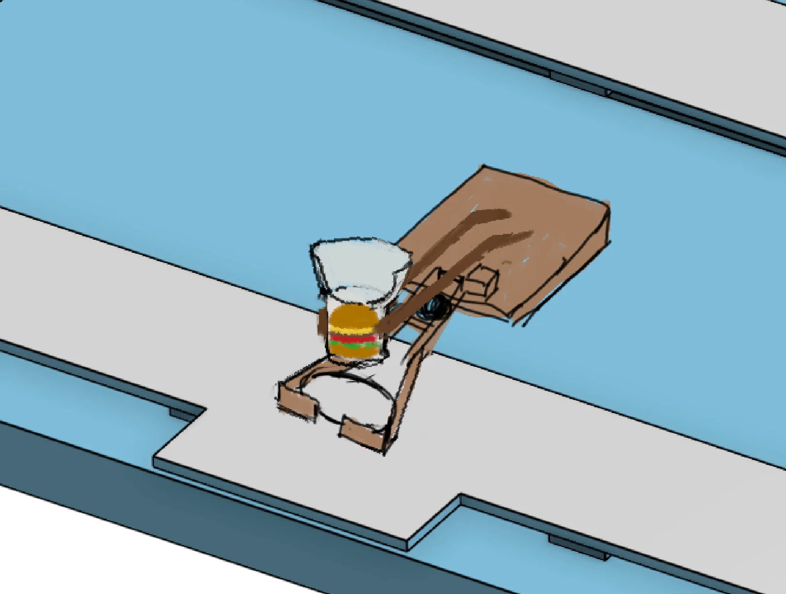
Preliminary Sketch of Burger Being Served
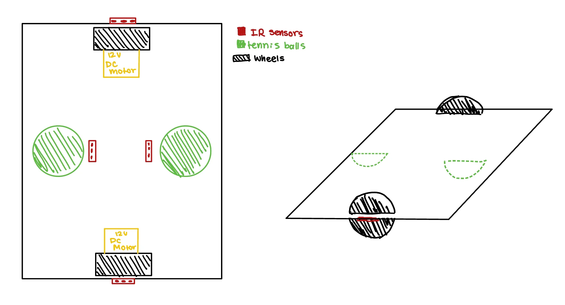
Initial Chassis Layout With Tennis Balls for Suspension
Initial Claw Proof of Concept
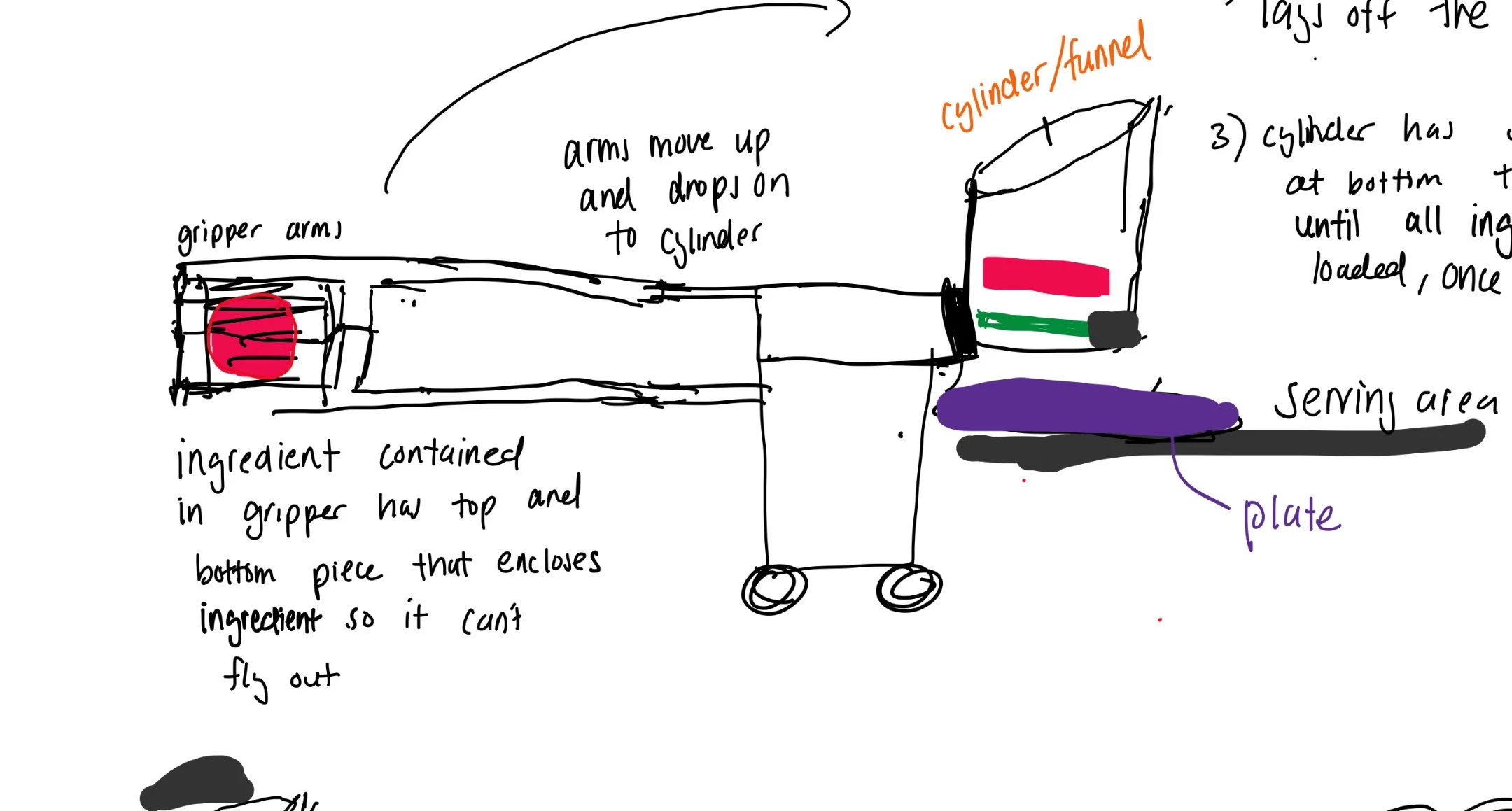
Inital Sketches of Claw and Chute Idea
One of my tasks during this project was to CAD the chassis. The claw and chute were designed by Tristan and Nathan
We decided to use two wheels, and two tennis balls for support. The tennis balls, though difficult to cut, worked surprisingly well! Their flexibility allows them to act as a suspension while the fuzziness lets them glide smoothly across the floor.
We designed the top half of our robot, holding the claw and chute, to rotate 180°. The reasoning was that we thought that operating a single servo would be easier than making our whole robot rotate (which runs the risk of becoming disoriented). In hindsight this feels a bit inelegant but hey, it still worked.
I cadded everything using OnShape and made an assembly to allow us to visualize where to mount servos and PCBs
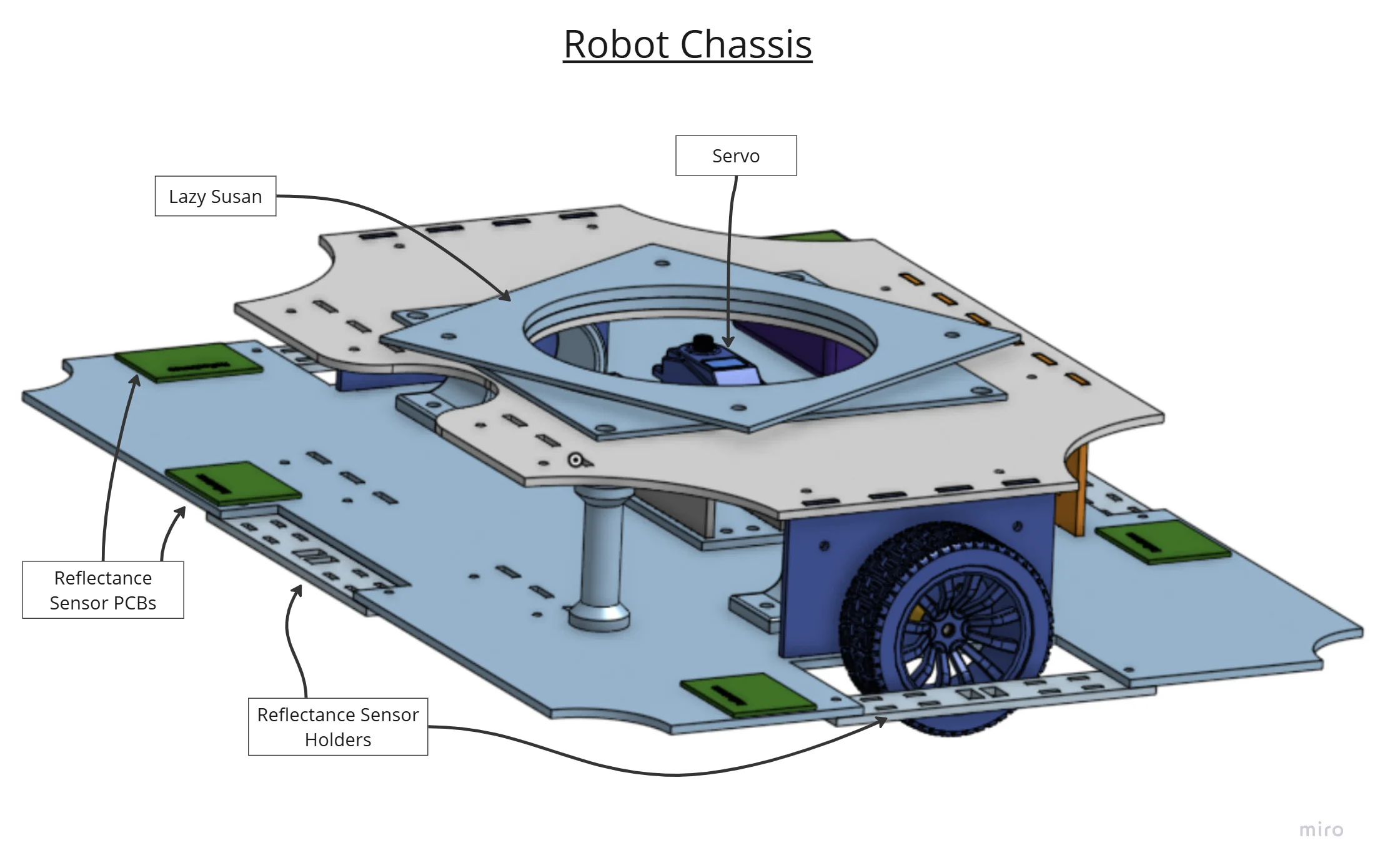
Assembly of the Robot Chassis, Reusable for Both Robots!
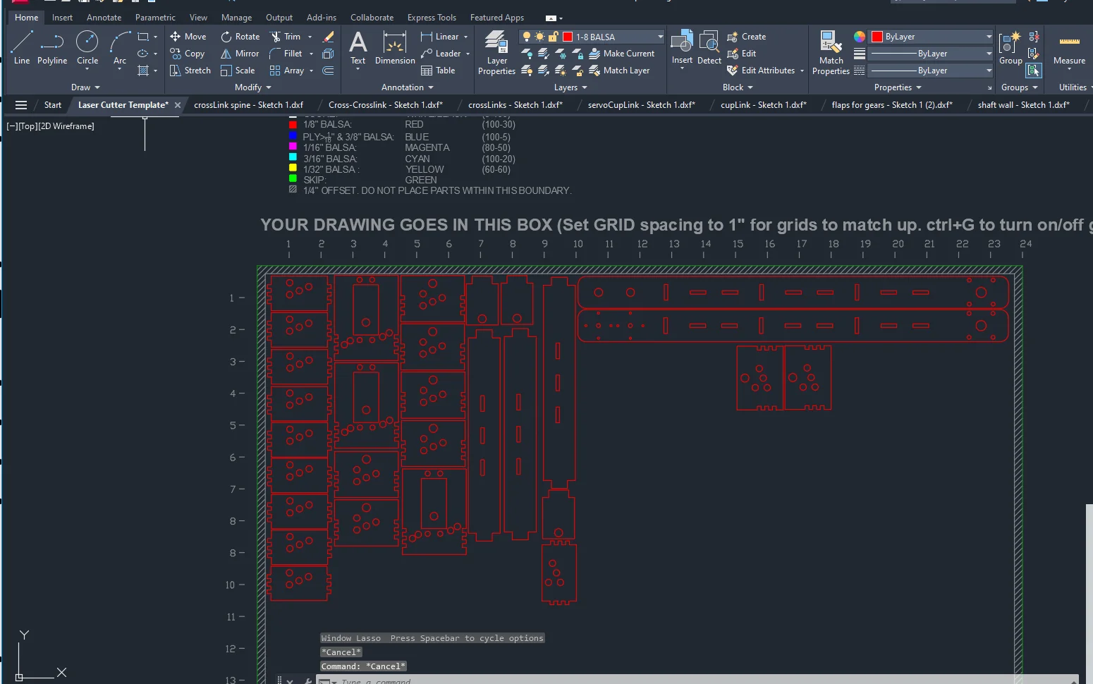
Nesting Claw Components for Laser Cutting
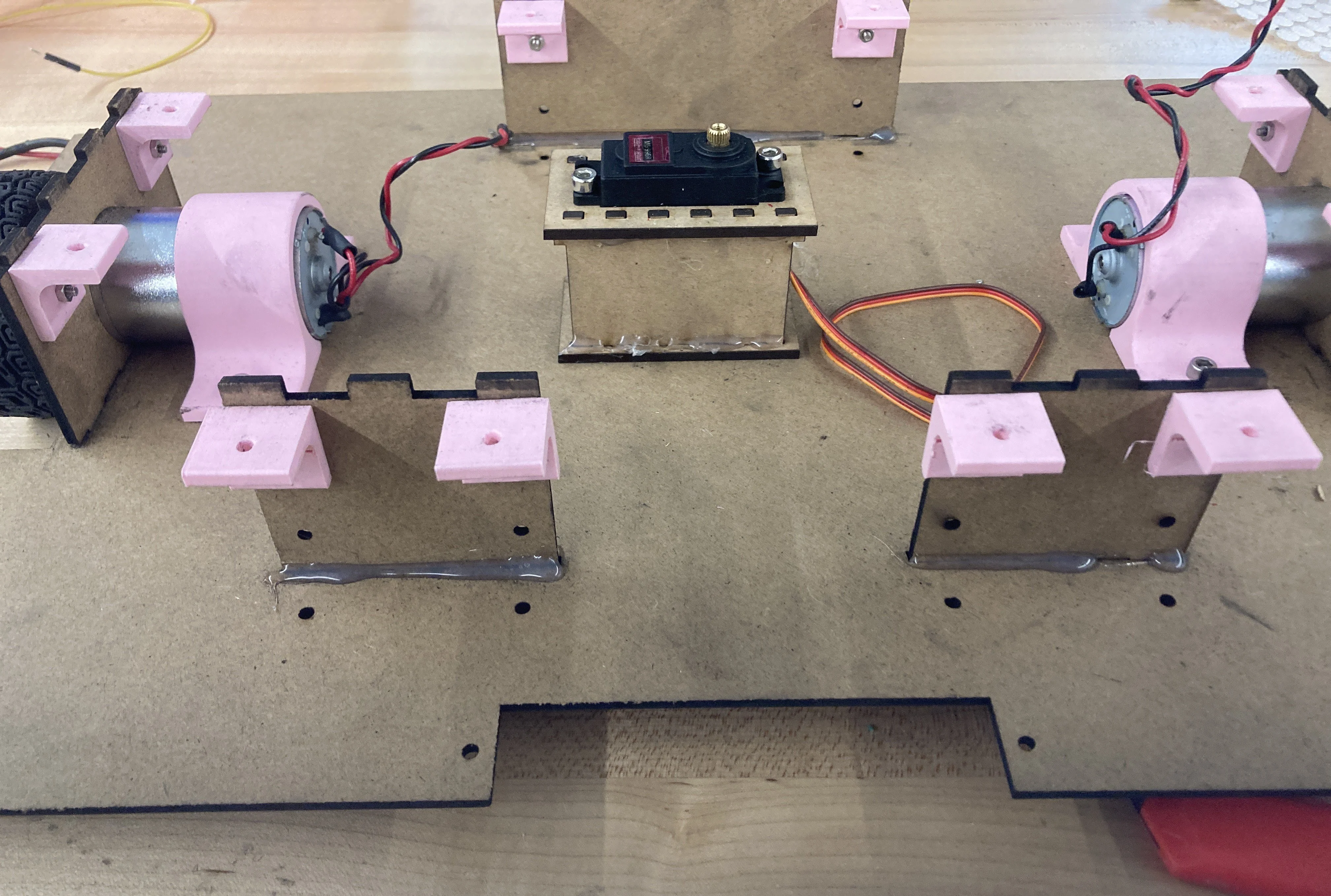
Partially Assembled Drivetrain
Testing Burger Serving Mechanism
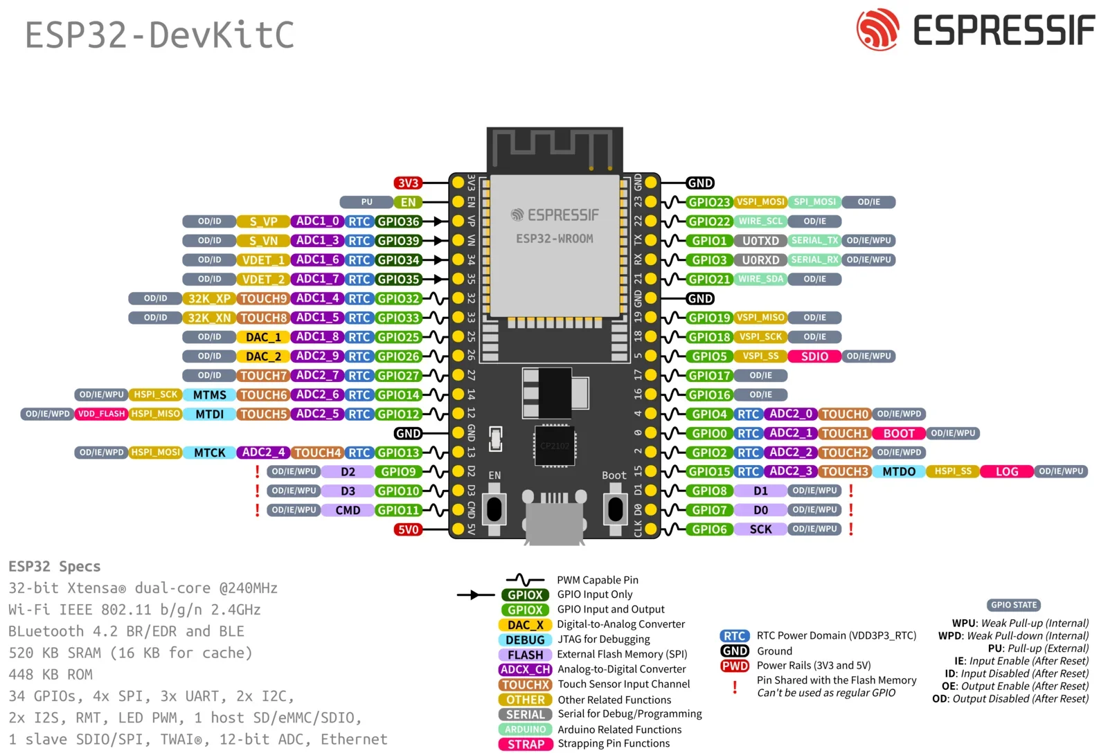
We chose to use ESP32's over bluepills as ESP32's come with built in wireless communication capabilities, namely WiFi, Bluetooth, and ESP-NOW. I also just happened to have a bunch lying around :3
One thing to note is that on a lot of ESP32 dev boards, some analog pins share hardware with the WiFi/wireless communication which renders them unusable when ESP-NOW/WiFi is in use! We learned this the hard way D:
This was our initial draft electrical block diagram generated during our planning phase. We ended up not using rotary encoders or IR beacon sensors (though Brianna's prototype was still really cool!). We also chose not to include the limit switches and IR beam breaks in the interest of time. We also changed our power system as this configuration causes too much power to be wasted by the LDO leading to brownout scenarios.
We chose give our motors a seperate ground as we didn't want the electrical noise to couple to our sensitive sensors and microcontroller.
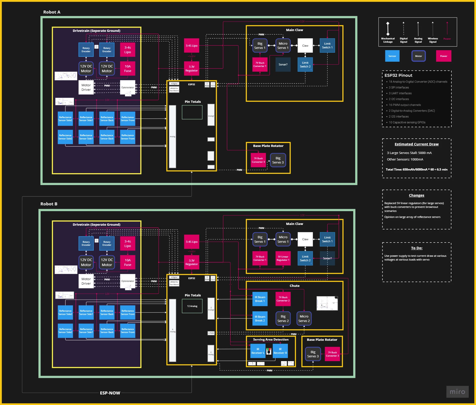
Initial Rough Electrical System Design
We made our own H-Bridge circuits to control our motors using LTC1161 motor driver ICs
On the right is an example schematic showing how to control a motor using the LTC1161. Our motor driver circuits used MCT6 optocoupleres to optoisolate the motors from the rest of our circuit to contain noise.
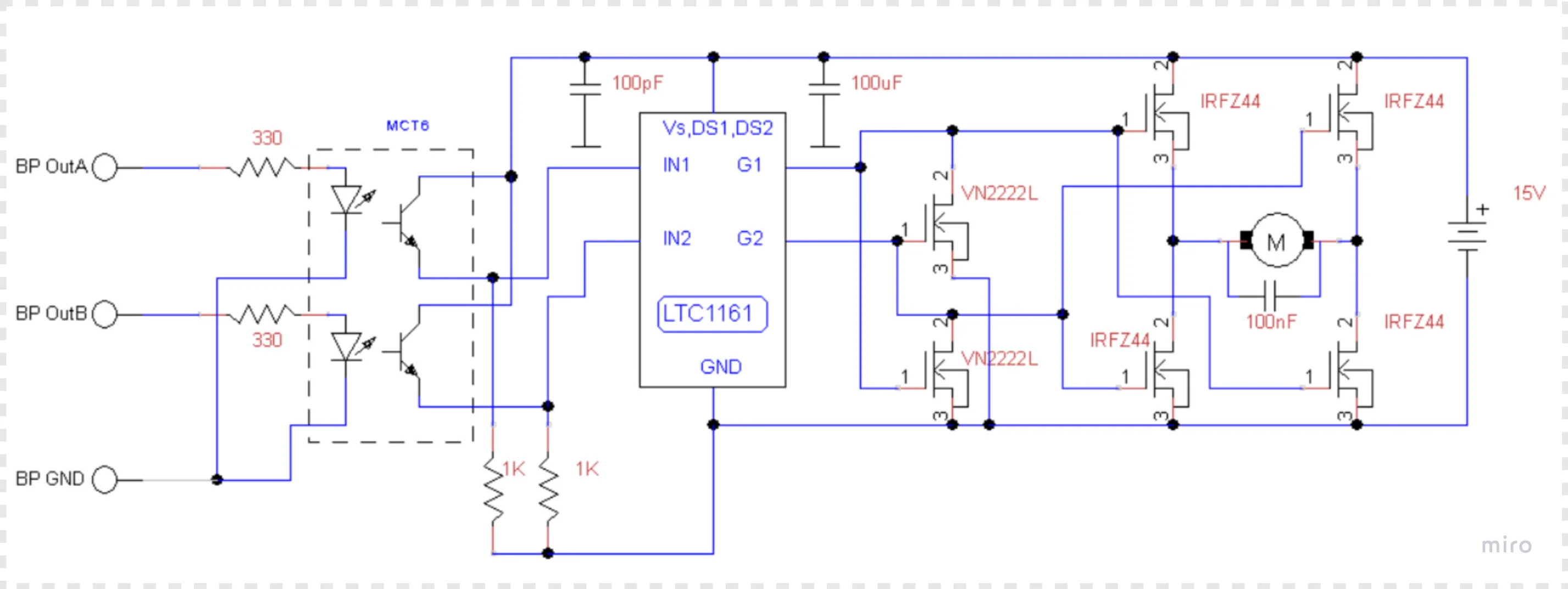
H-Bridge Example Circuit
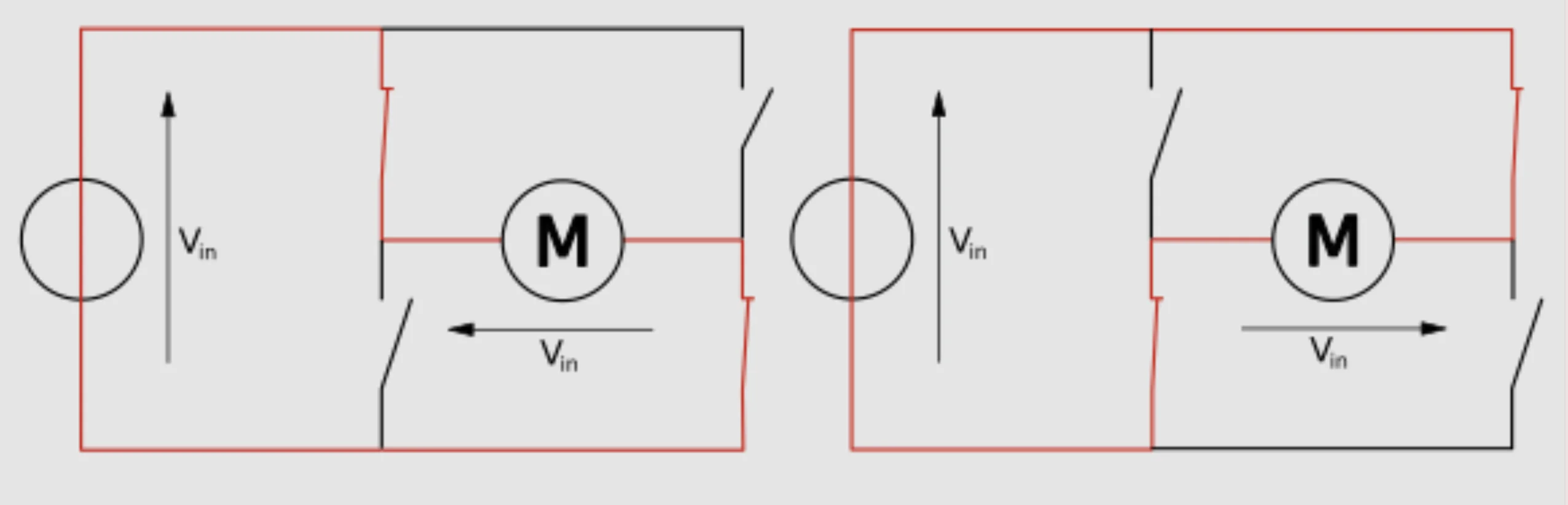
H-Bridge Swtiching Back and Forth
We chose to make PCBs to avoid having to solder multiple H-bridges by hand (and also for the learning experience).
The PCB features a circuit similar to the one shown above, but makes use of the fact that the LTC1161 can support two motors at once. It also featured testpoints and a power LED that came in real handy during debugging!
We chose to not use SMD components on our PCB, using only components available in our lab instead as we receive those components for free. This also made it a lot easier and cheaper to swap out faulty parts (cough cough MOSFETs).
My teammate Brianna made the PCBss while I reviewed them and gave her guidance/advice.
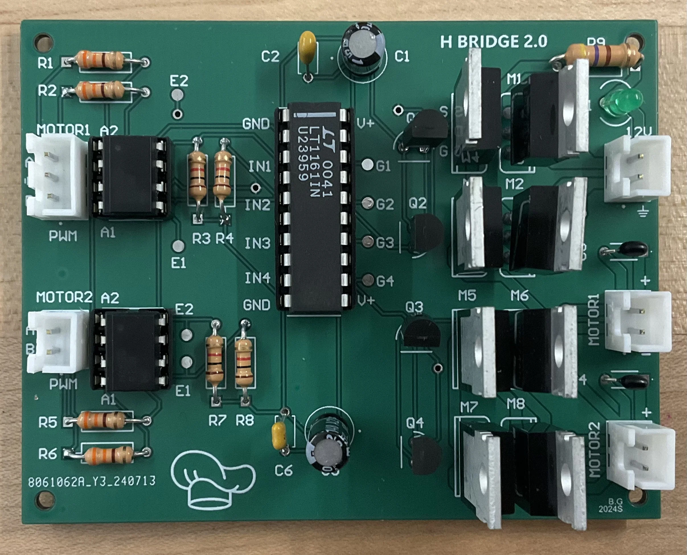
H-Bridge PCB Made by Brianna
We used TCRT5000s to detect the black tape on the white competition surface.
In our application, we pointed the TCRT directly down on the competition surface to detect the tape. When the TCRT shone on the black tape, the light would be absorbed and we would read a very high value. When the TCRT shone on the white competition surface, we would read a very low value.
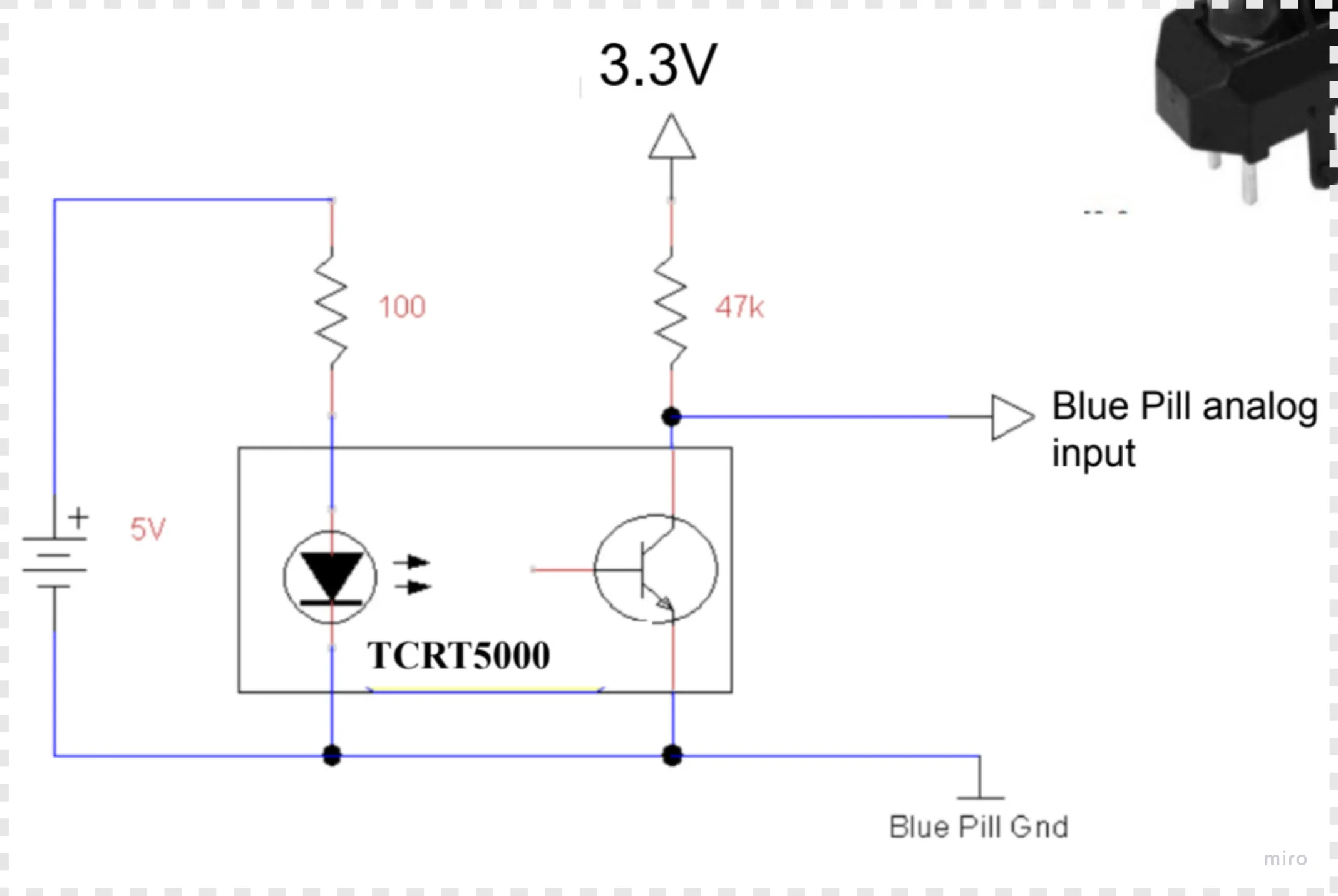
TCRT5000 Ciruit
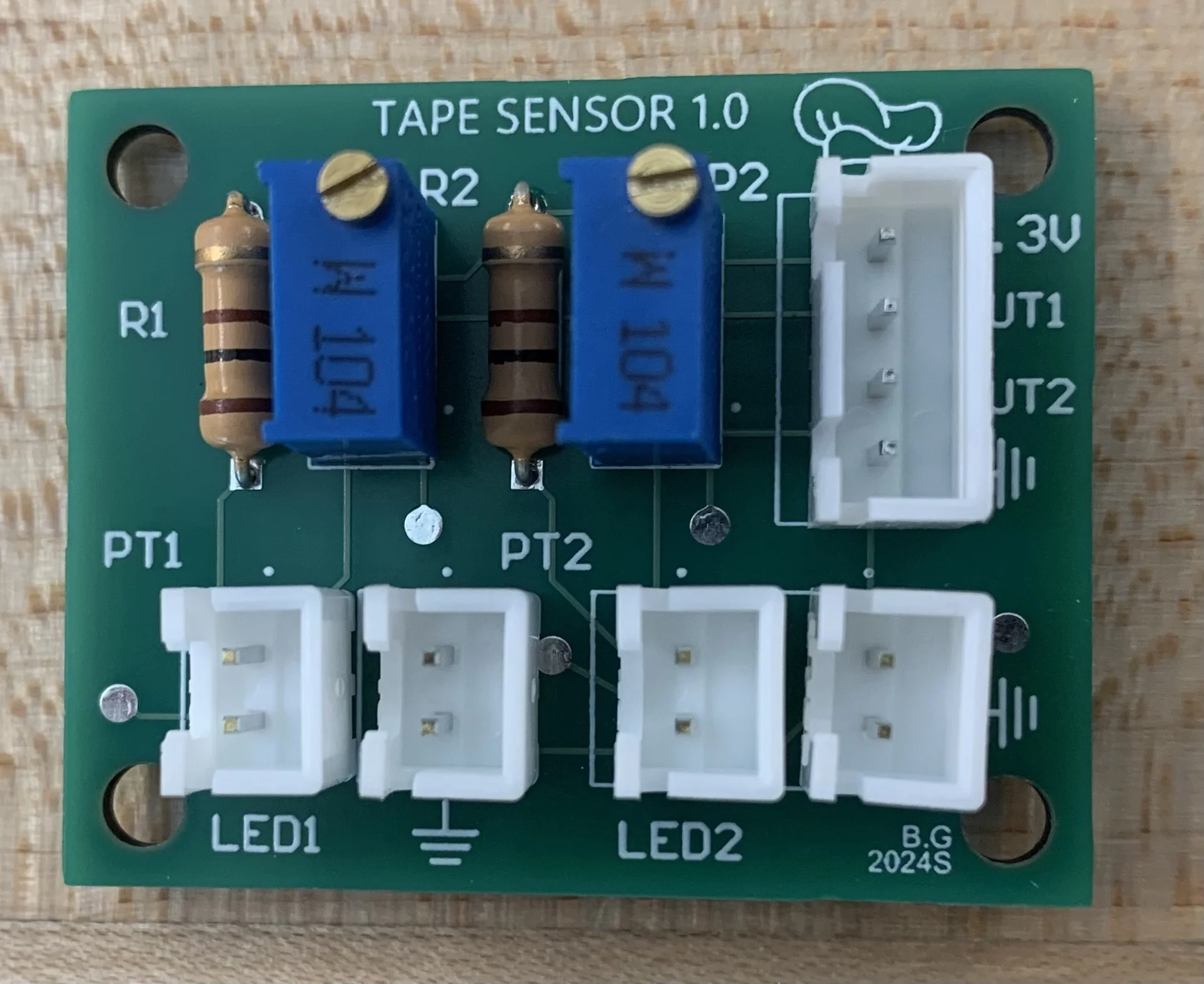
Reflecantce Sensor PCB
We used a combination of LM2596 buck converters alongside LM7805/LM7833 LDOs and 2s/4s LiPos to power our final system. Our motors were running off a 4s LiPo connected to a buck which stepped the voltage down to 12V. We also used a buck to step down a seperate 2s LiPo to ~5.5V for our servos. We then used LDOs to step the voltage further down to 5V and 3V3 for the rest of our circuitry.
We were initially so focused on other aspects of our robot that we made some very silly mistakes prototyping our power system. I don't know why we thought this was a good idea but we were stepping down ~16V to 5V and 3V3 only using LDOs. We didn't realize that the LDOs dropped voltage by wasting the excess power as heat. Our LDOs became insanely hot and shut down quickly. Here is a scope reading of our power board that haunts my dreams. If you're reading this please learn from our mistakes.
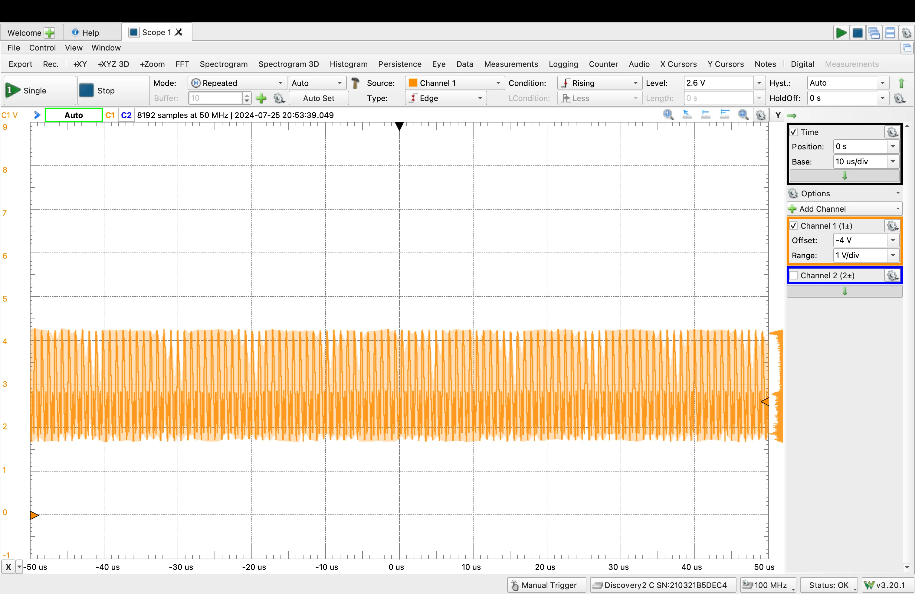
3V3 Line From My Nightmares
We originally used a state machine to organize our code. The list/order of tasks the robot needed to complete were very straightforward to implement with a state machine.
On the right I have the general block diagram that the two robots followed.
We wanted to organize sensors and other items into classes. For example, we made a seperate class for the motor with speeed/frequencing setting functions to keep our code organized.
Our code did end up becoming really messy at the end as we just cared about getting something working, rather than coding something maintainable, but the code was pretty well organized at the begnning which made rushing at the end easier.
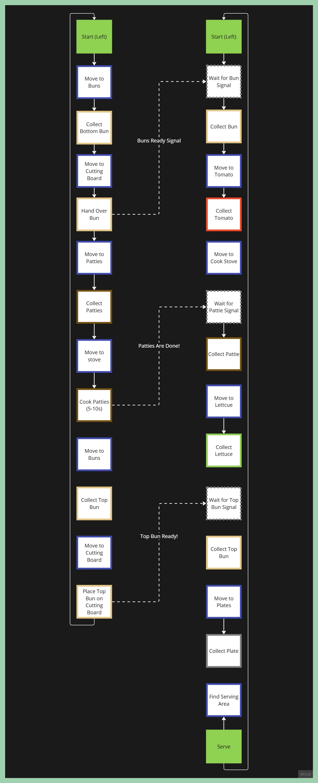
State Machine Block Diagram
We used PlatformIO flash code to the ESP32 over USB connection. Uploading code to the ESP32 was considerably slower than uploading code to the bluepill. This becomes a problem when you want to constantly adjust and tune parameters as you would have to wait 30s to reupload code each time you adjusted a parameter or wanted to add a print statement.
To circumvent this, I made a testing GUI using Tkinter to allow us to communicate with the ESP32 over WiFi. The ESP32 would connect to the school WiFi or a hotspot and then I could send HTTP post/get commands using the GUI on my computer.
This was extremely useful for tuning the driving control loop as we could simply send a new P error multiplyer over the WiFi and have it take affect instantaneously. We could also very easily write commands to the robot while it was in motion, allowing us to more easily characterize our robots behaviours.
Sorry it's lowkey ugly but it worked!
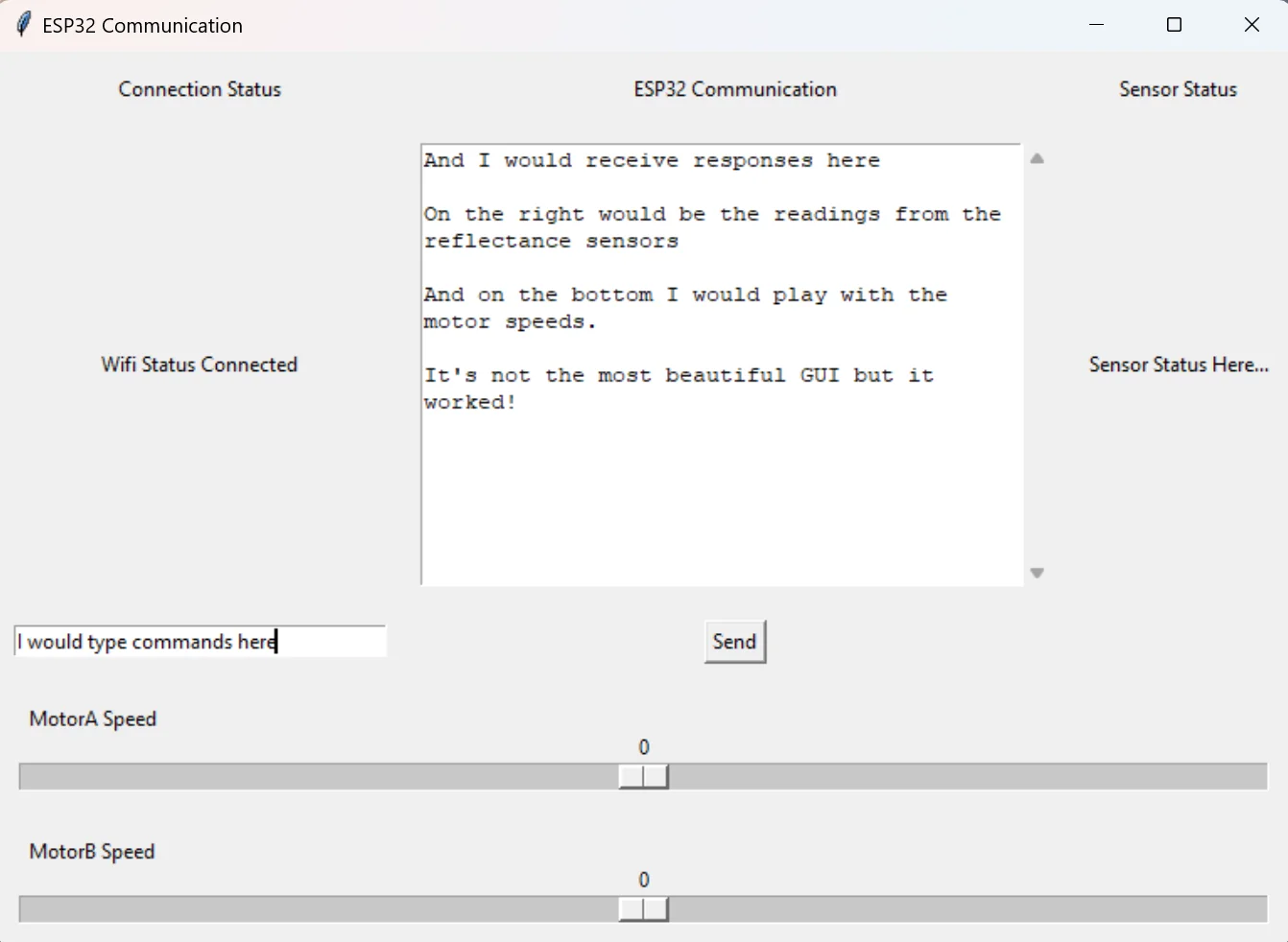
Testing GUI
We played aroud with PID line following but we found that stting I and D to 0 sufficed for our competition. I believe we mainly used P to stay on the line.
We also tracked where the last known location of the line was. If we went off the line, we would check if we went off to the right or left side of the line. Our algorithm was lowkey, "if on the line, don't be".
Anyway here's some really cool videos of the robot line following!
Resistance to Perturbations
POV Line Following